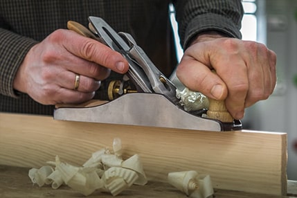
Build your own wooden plane

Building a wooden plane is not that difficult. We provide helpful tips to help you succeed. Here you can find out which tools and materials you need and we explain each step in detail.
We have largely followed the method described by David Fink in his book "Making and Mastering Wooden Planes". If you want to delve deeper into the subject of planing, we highly recommend this book. In our video , Peter Lanz shows you how to build a wooden plane in practice.
What tools do I need for planing?
- Marking tools: combination square, protractor, marking knife and pencil
- Saw for ripping (circular or band saw, can also be done by hand)
- Drill with 6 mm drill bit Saw for cutting the centre section (circular saw with angle stop, can also be done by hand)
- Block plane
- Chisel
- Possibly router with slot cutter (Ø 18 mm)
- hammer
- Glue, clamps and fixtures
- Rasp
- Tail plane
- Sandpaper
What material is required for planing?
You can actually use any hardwood for the planer box . Traditionally, copper beech was used in our latitudes. However, as beech is very strong, the planer box is usually glued from several pieces. You can also use oak, maple, ash, pear or service tree. The fine-pored woods have slightly better gliding properties than the open-pored woods. To protect the sole of the plane against wear, particularly hard wood such as hornbeam or even pockwood was used as a glued-on sole. In our example, we are using an oak planer box with a glued-on hornbeam sole.
The wood fibres should run as straight as possible through the planing block. If the grain runs at a slight angle, it should run diagonally backwards out of the soleplate so that you are working with the grain when using the plane. The orientation of the growth rings, upright, horizontal or diagonal, does not play a significant role. If the growth rings are horizontal, the side facing away from the core should be at the bottom.
You can use a used plane iron from an old planer. However, there are also very good new plane irons that are available especially for making your own planes. We use irons from Ron Hock, which are available in widths of 38, 45 and 51 mm. These irons are ideal for Krenov-style planes. They are not as long as the irons for a normal bench plane, and they are significantly thicker, which ensures smoother running when planing. They also have a perfectly aligned flap (chip breaker), which is also significantly thicker than other planing irons.
For the abutment, you need a square bar, 12 by 12 mm, with as straight a grain as possible and a brass base bar with a diameter of 6 mm. You will also need a few wooden dowels, preferably not fluted and also 6 mm thick, as an assembly aid.
The dimensions of the planer box blank are selected according to the intended use. The width of the planing iron used is decisive for this. As the planer box is first cut into a centre section and the two flanks, the saw cuts and the material that is lost by smoothing the saw cuts must also be taken into account. To ensure that the planer can be adjusted precisely, the centre section must always be slightly wider than the planing iron.
For the block plane (iron width 38 mm), the dimensions for the blank are as follows: Width: 2x flanks 8 mm + 2x saw cut 2 mm + centre section 41 mm = 61 mm Height: 55 mm Length: 180 mm
For the plaster plane (iron width 51 mm): Width: 2x flanks 10 mm + 2x saw cut 2 mm + centre section 54 mm = 78 mm Height: 60 mm Length 240 mm
For the long finishing plane (iron width 45 mm): Width: 2x flanks 10 mm + 2x saw cut 2 mm + centre section 48 mm = 72 mm Height: 60 mm Length: 330 mm
The dimensions given here are to be seen as an example and reference point and can be changed according to your own requirements.
How can I build a wood plane myself?
In the following, we will go through the individual work steps in sequence:
1. marking out the grain pattern, triangle.
So that nothing gets mixed up later, draw the grain pattern on the sides and a triangle on the top with the tip pointing in the direction of use.
2. cutting open the blank.
The cross-section of the blank should be planed out at a perfect angle. Cut off the flanks from both sides to the required thickness so that the remaining centre section is at least 1 to 1.5 mm wider than the planing iron after planing again. The two flanks are also planed on the cut surfaces (inner sides). Cutting and joining can be done with hand tools. It is easier and more precise with a circular saw or band saw and thickness planer.
Fig.: The planer box is glued from three parts

3. drill dowel pins.
To ensure that the flanks can later be glued back to the centre section with an exact fit, first drill holes for dowel pins in the upper corners, which will be omitted during the subsequent shaping. The dowels used for this should preferably not be fluted and should fit tightly. To prevent them from cancelling out the clamping pressure of the clamps when gluing, the dowels are shortened so that they are exactly flush with the surface of the flanks.
4 Mark out and saw out the planing box opening.
The block of flanks and centre section can be levered apart again using a chisel. Set the two flanks aside first so that they are not accidentally sawn apart with the centre section. We now cut the cut-out for the plane iron and the chip passage on the centre section. The angle of the iron is 45°. The plane mouth should be approx. 5/9 measured from the rear. The point at which the cutting edge meets the sole of the plane is determined by placing the plane iron against the mitre angle.
Fig.: Dimensions for the opening in the planer box and the position of the abutment

Draw a 3 to 5 mm long line from this point, at a right angle from the sole of the plane upwards. This is where the front edge of the planer mouth will later run. Only from here is the angle for the chip breaker scribed at 62°. Now the centre section of the planing block is sawn. Hand tools can be used again for this. However, it is much easier and more precise with a circular saw with an angle stop. You should not yet cut the straight edge on the planer mouth exactly to size. The planer mouth is adjusted precisely after gluing together.
Important: Do not throw away the remaining piece when sawing the centre section, it will be used later to make the wedge!
5. hole for abutment.
The centre of the hole in the planer box is 30 mm from the bottom edge (planer sole). For exact positioning, the rear ramp is again plugged together with the flank. With the help of the plane iron and the chip breaker, the position of the abutment can now be precisely measured and scribed. The gap between the chip breaker and the abutment should be 5 mm; this is where the wedge will be inserted later. Now drill a flank first, preferably on the pillar drill, using a 6 mm drill bit. Once the second flank is also connected to the centre piece, you can drill through the hole into the second flank from the other side.
Fig.: The planing block is put together to drill the abutment

6. manufacture the abutment.
The abutment consists of a brass axle and a wooden block slid over it to improve pressure distribution. The length of the wooden block should be shorter than the width of the centre section. Due to the different shrinkage behaviour of the abutment and the planer box, the abutment could otherwise crack the planer box. To drill the centre of the abutment, diagonals are drawn at both ends and drilled from both sides towards the centre. To ensure that the hole runs as straight as possible through the block, you can make a moulding with an incision into which the block can be clamped. The axle should be slightly shorter than the overall width of the planing box so that it does not interfere later when cleaning the outer sides. The ends are slightly chamfered. Round off the top of the wooden block.
7. cut-out for chip breaker screw.
Before the plane can be glued, the cut-out for the head of the chip breaker screw must be made. If a router with a suitable cutter and two rip fences is available, this can be done very quickly and easily. Alternatively, a template can be made for the thrust ring or you can chisel out the recess by hand. The recess should be large enough so that the plane iron can slide forward to the sole of the plane and also has enough play at the sides for adjustment.
8 Glueing.
To ensure that you do not forget the abutment in the next step, it is best to insert it into one of the two flanks first. In order to align the front and rear parts quickly and precisely, clamp an allowance against the underside of one of the two blocks. Now apply glue and attach the corresponding flank. Then apply glue to the second block and also attach it to the flank. By attaching a second clamp, you can now align the two parts exactly with the help of the allowance. Then apply glue to the second flank and attach it. Attach a sufficient number of clamps. You can remove any excess glue directly.
9. produce the wedge.
The waste from the centre piece is large enough to make the wedge. Mark the thickness and bevel of the wedge. You can come up with a nice design for the top edge. We have marked a thickening that is rounded. This shape is modelled on a wood shaving. Cut out on the band saw, smooth the cut surfaces and reduce the width slightly with a plane, and the wedge is quickly prepared for fitting later.
10. adjust the wedge and planer mouth.
Once the glue on the planer box has hardened, you can insert the iron and the wedge for the first time. If the wedge jams on one side, it must be adjusted so that it clamps equally across the entire width of the abutment. If the sides of the planer box are too high to adjust the iron and wedge, first cut them back roughly. Now you can adjust the front edge of the planer mouth. To do this, file it away so that the chip gap is nice and small and parallel to the cutting edge. Caution: Do not drive the iron through the mouth of the plane too early, as this can lead to chipping on the underside. The edge of the plane mouth should remain as sharp as possible!
11 Flatten the sole of the plane.
Using sandpaper, the sole of the plane can now be planned on a flat surface (e.g. on a machine table). You can then use the planer to remove the first chips - provided the planer blade is sharp.
12 Shaping and surface.
We draw the desired silhouette on one side of the planing box and saw out the shape with the band saw. If no band saw is available, rasps can also be used. However, you should remain square to the sides of the box while working. The edges are only rounded off after the lines for the bevelled edges have been marked. The intermediate step of first making bevelled edges makes it easier to ensure that both sides are symmetrical and the curves are harmonious. The side edges of the plane sole can be slightly bevelled before the surface is sanded.
Fig.: The planer box is given its shape with tail planes, rasps and files

13. surface treatment.
Finally, you can oil the plane (e.g. with ASUSO NL hard oil) or coat it with two to three coats of shellac . The sole of the plane remains untreated. To make the plane glide better, you can polish the sole with paraffin wax and wood shavings.
Conclusion: Build your own wood plane
Building a James Krenov-style planer yourself is a great project for any tool enthusiast. You will get to know your tool in a completely different way and appreciate it all the more.
Our workshops give you the opportunity to familiarise yourself with a wide range of tools. In addition to numerous courses for woodworking, we also offer sharpening courses for your knives and tools as well as courses for metalworking.