The Shinko DH330 thickness planer is easy to maintain. In normal usage (non-commercial use), it is very robust and only requires the usual maintenance and cleaning tasks. Being able to properly check and readjust your DH330, however, is essential for ensuring permanently optimal planing results.
Safety first! For all of the following activities (setting, checking, adjusting, etc.) that do not involve planing, the machine must be completely disconnected from the mains power supply - pull out the mains plug! Switching off alone is not enough to avoid serious injuries.
Checking and setting the scale
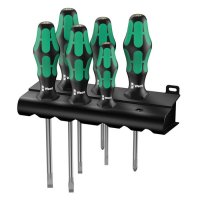
The scale on the front of the machine shows the expected thickness of the finished workpiece. To ensure that the scale is set correctly, plane a piece of wood and then measure its thickness. If the scale is not set correctly, loosen the two round-head screws securing the indicator and set the thickness indicator to the correct value. Then hand-tighten both screws again. Done!

The scale can be moved up and down by a total of 3 mm.
Aligning the table extensions (infeed and outfeed tables)
Both fold-out tables serve only as a support or tilt protection, i.e. the infeed table facilitates feeding the wood and the outfeed table ensures that it does not tilt or fall off after planing. The alignment of the tables has almost no influence on the planing result. During planing, the workpiece is pressed onto the inner planing table by the two transport rollers.
Plane marks, grooves or indentations at the ends of the workpiece can occur if the workpiece is not properly supported on the outfeed table. Longer workpieces in particular tend to tilt as soon as they are no longer pressed onto the machine table by both the infeed and outfeed rollers. If the infeed roller no longer exerts pressure, the rear end, which is then directly on the cutterhead, can shoot upwards. This results in the typical planing marks. The outfeed table must therefore be adjusted so that it supports the workpiece level to the machine table for as long as possible.
The infeed table should also be flush and parallel with the planing table so that the workpiece can be fed directly and without resistance. Both tables can therefore be aligned and levelled.
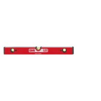
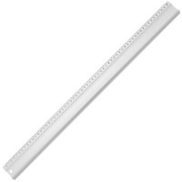
In order to check and align the folding tables, you need a long steel ruler, a spirit level or a straightedge.
First check that the infeed table is at the same height as the planing table. This is done by placing the ruler on the planing table and a little way over the infeed table and checking whether the ruler rests flush over its complete length or whether a chink of light can be seen. If light can be seen on the infeed table, it is set too low. If light is visible on the planing table, the infeed table is set too high.

You can check the alignment of the infeed and outfeed tables with a straightedge or a spirit level
If you need to adjust the height, first fold up the table. There are two stop screws with locknuts on the housing. Once you have loosened the locknut, the stop screw can be turned up or down. If you cannot loosen the lock nut, use some penetrating oil. Then fold the table down again and check whether the correction was sufficient. If the infeed table is exactly level with the planing table, tighten the locknuts again.
Next, check that the infeed table also runs parallel to or flush with the planing table. Place the ruler over the entire length of the planing and infeed tables and check again whether a light gap can be seen anywhere.
If you need to level the infeed table, loosen the Phillips screws on the sides of the table - do not unscrew them, just loosen them - and slide the internal metal struts up or down, depending on whether you want to raise or lower the end of the table. Then retighten the Phillips screws and check the level of the infeed table again. The height may need to be adjusted a second time.
The same adjustments can be made to the outfeed table. Alignment is even more important here than at the infeed table, as a misalignment at the outfeed table can lead to planing marks at the end of the workpiece. The procedure is exactly the same as for the infeed table.
Readjusting the preset planing thicknesses
The DH330 has a slider with eight predefined thicknesses (3 / 6 / 12 / 19 / 25 / 30 / 38 / 44 mm) on the side below the handwheel. The slider can be moved to the left or right to set the desired material thickness. This function is particularly practical when planing several workpieces when the settings have to be changed several times in between. The first step for checking the settings is to plane out a piece of wood and measure the thickness.
If a deviation of the same value occurs for all thicknesses, correction is relatively simple. Turn the motor block to the uppermost position. There is a pendulum protection flap below the hand crank. Push it to the left. Inside there is an adjusting screw with a locknut. This screw acts as a stopper and engages when adjusting the passage height. First loosen the locknut before adjusting the adjusting screw. Tighten the locknut firmly again before starting a planing test to check the set passage height.
If only one preset deviates or if several settings show different deviations, the adjustment is somewhat more complex. So far we have received no queries about this, but we would still like to explain it briefly.

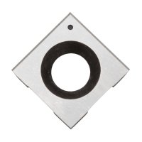
The preset planing thicknesses can be adjusted by turning the stop screw.
Pull off the knob on the slider and loosen the screw on the thickness presetting cover. Behind it is the stepped spacer. If you loosen the two/three screws, you can remove the fence. The spacer is made of die-cast zinc. You can file down the steps if one of the thickness presets is too high. If one of the presets is too low, material would have to be glued onto the step, which is difficult. But as we said, so far this has not yet occurred.
Tips for good planing results
Planing on both sides
Always plane the workpiece on both sides and always use approximately the same chip removal/cutting depth to achieve the desired thickness. Since there may be more moisture inside the wood than on its surface, boards or planks may warp if material is removed mainly on one side.
Last planing pass with little removal
Planing passes with less material removal provide a smoother surface than rough cuts with maximum material removal. Use a coarser chip removal (1.5 to 3 mm, depending on the material and dimensions of the workpiece) first to quickly remove material. Reduce the material removal rate the closer you get to the desired final dimensions and remove only 0.2 to 0.3 mm of wood in the last planing pass.
Support long workpieces
Long squared timbers and battens tip off quickly after they have passed the outfeed roller. Especially with heavier squared timbers, there is a risk that they will then hit the machine housing. This can lead to defects in the wood and, in the worst case, to the planer falling over. Therefore, support long and heavy workpieces on the outfeed side with a roller trestle or take them directly at the outfeed table. However, avoid pulling or lifting while the workpiece is still being transported by the outfeed roller.