You should check a few settings from time to time to make sure that your surface planer works perfectly. As the name implies, the surface planer is primarily used for planing workpieces. This means that a flat surface should first be created on the workpiece. For this purpose, it is necessary that the take-off table is exactly level with the highest point of the planing knives, the so-called flying circle, and that the feed table runs parallel to the take-off table. From time to time, you should check the machine tables to see if the settings are still correct and readjust them if necessary. This is especially important after the jointer has been transported.
How to check and adjust the pick-up and feed table?
Attention: Before starting maintenance and assembly work on the machine, disconnect it from the mains by pulling out the mains plug! Turning off alone is not sufficient.
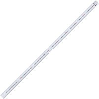
For the following maintenance work you will need the »on-board tools« supplied, a precision rule or straightedge approx. 1 m long (alternatively a spirit level), a 10 mm screwdriver and a thin drill bit (e.g. with Ø 2 mm).
To be able to turn the cutter safely and see all the insert knives clearly, you must remove the cutter cover. To remove the cutter cover, loosen the locking screw at the lower end of the holder and pull the whole cover out of the guide. Now you can use the 4 mm hexagonal spanner in the opening in the cutter head to turn it safely.
Caution: The cover is an important protective device. The machine must never be operated without the cover! It is essential to remember to refit the cover after finishing the fine adjustment.
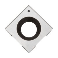
Checking the take-off table: The first step is to check and adjust the take-off table. Therefore, lower the feed table slightly. Bring the cutting edge of an insert knife at one end of the shaft to its highest point, and check with an applied straightedge whether the table is too high or too low at this end. Then check the table height at the other end of the cutter. The cutting edges should noticeably touch the straightedge, but not dig into its surface.

Does the take-off table run at the height of the cutter head?

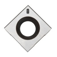
The height is adjusted by turning the screw socket.
Screw sockets hidden under the four screws in the table are used to adjust the take-off table. Remove the necessary screws and adjust the table by turning the screw socket with the 10 mm wide screwdriver. Turning clockwise moves the table upwards, turning counterclockwise moves it downwards. To be able to check the changed settings, all screws must again be screwed in tightly, as they fix the table. If necessary, you may have to unscrew the screws a few times and readjust them. When everything is correct, all insert knives should always lightly touch the straightedge.
Checking and adjusting the feed table: Next, check that the feed table is parallel to the take-off table. To do this, set the feed table at the chip thickness adjustment so far upwards that it just touches the straightedge placed on the take-off table. The feed table should run parallel to the straightedge over its entire depth. If necessary, adjust the feed table in the same way as for the take-off table by removing the screws and adjusting with the screw sockets.

Use a drill as a feeler gauge to check the alignment of the feed table.
To check whether the feed table runs parallel to the take-off table with the chip removal set, you can use a drill as a feeler gauge. Place the drill between the feed table and the straightedge and adjust the chip removal so that the drill can just be pushed between the feed table and the straightedge. Now you can check the distance at different places. The drill should be able to be pushed just enough between the table and the straight edge everywhere. If this is the case, both tables are optimally set up again.
How are the table extensions of the AH200 adjusted?
As long as the cutter cover is still removed, you can check the table extensions on the AH200 jointer. First, see if the extension rods can be moved without play. If they go very strictly or have too much play, you can adjust this at two nylon screws under each table. To complete this, loosen the lock nut with a ring or open-end spanner SW 8, readjust the nylon screw and then secure it again with the lock nut.
The crossbar of the table extension can be adjusted in height by twisting the extension rods. The crossbar is secured with screws from below. Loosen these securing screws with the 4 mm Allen key. Now you can use the same spanner to turn the eccentrically mounted rods so that the crossbar is at the same height as the table. Then secure the extension rods again with the locking screws.
Do not forget to refit the cutter cover!

The AH200 offers two adjustable extensions as table extensions.
How are the stops of the joining fence adjusted?
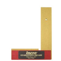
When one surface of the workpiece has been dressed, one of the workpiece edges is usually subsequently joined at an angle. To accomplish this, you need a joining fence that is set exactly at a right angle. Check the angularity every time you use it by applying a precision square. The fence should be adjusted using the precision square if the angle is not correct. To be able to change the angle of the joining stop more easily later, turn the right adjustment screw of the stop so far that it touches.

The joining stop is controlled with a precision square.
The joining stop also has a stop with an adjustment screw for the 45° position. With a mitre angle, you first set the joining stop at an angle of 45° and then turn the adjusting screw accordingly. Now, working with your Shinko jointer should work precisely again.

Readjusting the screw on the jointing fence