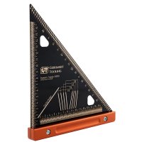
Successful wood joints begin with accurately marked out joints. The Engineers Triangle 200PCB is an all-rounder for many jobs involving checking, measuring and marking distances and angles. It also has features that simplify marking for woodworkers. In this post you will learn more about this practical workshop accessory.
Benefits of the Engineers Triangle 200PCB
Versatile: the Engineers Triangle 200PCB is more than a simple carpenter’s square. You can use it to check distances and spacing, accurately mark out angles to a half of a degree accuracy, determine the centre of an object and scribe dovetails in four different pitch ratios. The Engineers Triangle combines the features of a ruler, carpenter's square, protractor, marking gauge, centre finder and dovetail template in one single marking tool.
Reliable precision:the blade on the Engineers Triangle 200PCB is made of FR4 PCB material, which remains dimensionally stable even with temperature and humidity changes. Even its manufacturing process is on a par with printed circuit boards with just as high accuracy.
Nice and clear: thanks to the light, gold-coloured lines and numbers on a dark background, all the scales and values on both sides of the blade are easy to read. This means reading and transferring is much more accurate.
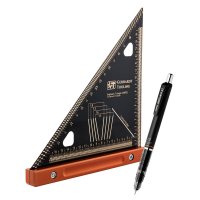
Pleasant feel and nice handling: all the corners are rounded off. This means that the Engineers Triangle 200PCB not only sits comfortably in the hand, but the corners don’t catch on anything. With its robust CNC-milled aluminium fence, it reliably sits and aligns with the workpiece edge. Marking slots in the shape of small oblong holes makes it easy to precisely position a sharp pencil or a 0.5 mm mechanical pencil (e.g. Zebra »DelGuard« Mechanical Pencil).
Marking distances and parallel lines:
For measuring length and spacing, the Engineers Triangle 200PCB has two scales with marking slots at one-millimetre increments. By using a mechanical pencil in the appropriate slots and moving the workpiece, you can draw lines parallel to the workpiece edge — like with a marking gauge.

The Engineers Triangle helps you to precisely measure and mark out mortises
Measure and mark out angles:
The Engineers Triangle helps you to mark out angles to a half degree accuracy. We explain the two ways to do this below:
1. To mark out an angular deviation from 90 (e.g. from the short edge), align the Engineers Triangle with the blade at 90 and place it with the fence on the long edge. Now find the desired angle on the degree scale and tilt the Engineers Triangle until the appropriate marking slots lie exactly over the long edge.

Angular deviation from 90°
2. To scribe an angle, going from any point on the edge, place the Engineers Triangle against the edge and align it with the starting point. Then look for the desired angle on the degree scale and mark it with a dot on the surface. Now you just need to connect the two dots to achieve the desired angle of inclination.

Perfect angle, outwards from one point on the edge
Marking the centre line or centre:
To mark the centre on the end face of squared timber place the Engineers Triangle 200PCB with the fence vertical and lay the workpiece with the end face against the blade and the fence. Then draw a line in the centre finder’s slot. Now tilt the workpiece by 90 and draw a second line: the intersecting point is the centre point. The procedure is similar for round or cylindrical workpieces (e.g. blanks for woodturning). These are also placed on the blade of the upright Engineers Triangle. Draw several lines using the centre finder over the end face, turning the workpiece occasionally. Again, the intersecting point of the lines is the workpiece's centre axis. If your workpiece isn’t quite round and the lines don’t meet in one point, then a small unedged area arises, whose centre is again the centre of the workpiece — you can now easily gauge this.

The centre finder simplifies finding and marking the centre point
On rectangular workpieces you can determine a centre line by drawing a diagonal (45 ) outwards from each corner. The intersecting point of the two diagonals is at the centre axis. By connecting the two intersecting points you can find the desired centre line.
Scribing dovetails:
You can use the Engineers Triangle 200PCB to scribe pins and tails with four different pitch ratios: 1:5, 1:6, 1:7 and 1:8. To do this, as usual start by drawing the points of the pin factor on the centre line of the workpiece’s end face. As the marking slots for dovetails start with a spacing of 20 mm to the aluminium fence, set a batten with at least 20 mm thickness between the fence and workpiece. Now you just need to move the marking slots of the desired pitch over the marking of your pin factors to mark the pins.

The points of the pin factor are clearly visible in the marking slots